555 Timer
This circuit is a 555 timer in astable mode, which generates a continuous square wave signal. The LED connected to Pin 3 (Output) will blink on and off at a frequency determined by the resistor and capacitor values.
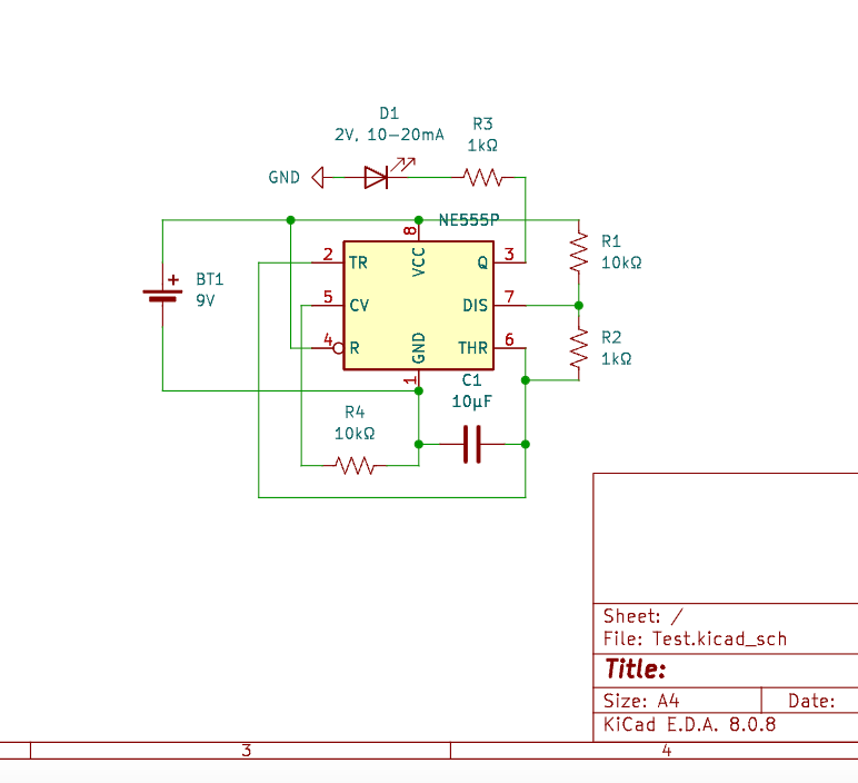
Schematics
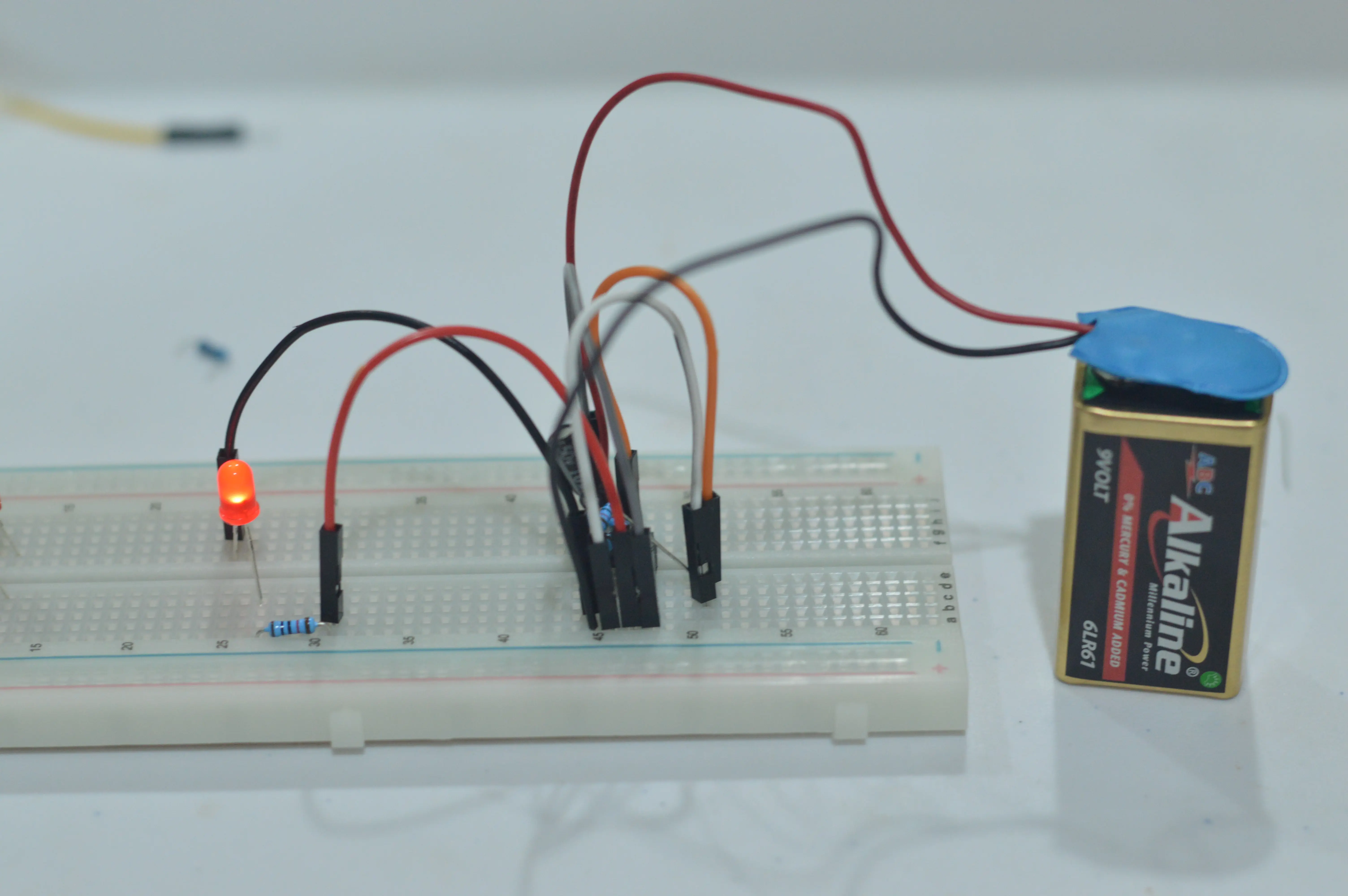
On Breadboard
This circuit is a 555 timer-based astable multivibrator, designed to generate a continuous square wave signal. By using a combination of resistors and a capacitor, the circuit controls the timing of the output pulse, causing an LED to blink at a steady rate. The 555 timer operates by repeatedly charging and discharging the capacitor, switching the output between high and low states. The LED, connected to the output pin, turns on when the output is high and off when it is low, resulting in a flashing effect. The frequency of blinking is determined by the values of the resistors and capacitor, which can be adjusted to modify the speed of the LED’s flashing. This simple yet effective circuit is commonly used for clock pulses, LED indicators, and basic timing applications.
How It Works
- The 555 timer continuously switches between high and low states, creating a pulse wave output.
- The frequency and duty cycle of the blinking LED are controlled by the 10kΩ and 1kΩ resistors and the 10µF capacitor.
- Since Pin 2 (Trigger) and Pin 6 (Threshold) are shorted, the capacitor charges and discharges repeatedly, cycling the timer.
- The LED blinks as the output switches between HIGH and LOW.
Other Projects

A basic heart-shaped 5mm led powered by 9V battery with a 10kΩ resistor.